Place fixpoints and sliding elements correctly
07 December 2021 , Volker Weber, Produktmanager
Rule of thumb: Up to 10 meters length in residential construction uncritical
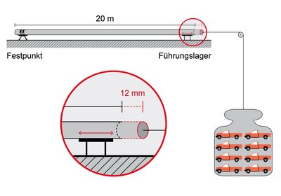
A riser with a height of 20 m is certainly not unusual in residential construction. If this pipe is the heating flow, temperature fluctuations in the range of 15 to 65 °C can be expected over the course of the year, so about 50 K. For a steel pipe, these numerical values result in a change in length of 12 mm according to the formula for thermal expansion - the calculations can be found in the info box "Thought experiment on thermal expansion". Whether 12 mm is a lot or a little can be determined with a thought experiment, namely by asking what forces a construction would have to apply to compensate for this expansion. Or, to put it another way: What forces would have to be applied to compress the heated pipe in order to reverse the change in length? A DN 100 steel pipe was selected for the calculation. This results in a force of 157 kN, which is roughly equivalent to the weight force of eight American design pickup trucks.
The weight force of 16 tons is required to achieve the same effect as 50 K temperature increase for a 20 m long DN 100 steel pipe. The same amount of compressive force would also be required to compensate for the thermal expansion.
What does this mean in practice? If the change in length of such a riser is not controlled safely, the pipeline will look for a resistance and apply forces of 0 to 157 kN to it - structural damage will hardly be avoided. For comparison, another figure: The pipe with water filling and insulation has a weight force of 6.35 kN in this example. Forces due to impeded thermal expansion can therefore easily exceed the forces on which the design of the bearings is based by a factor of 10 or more.
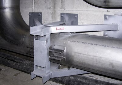
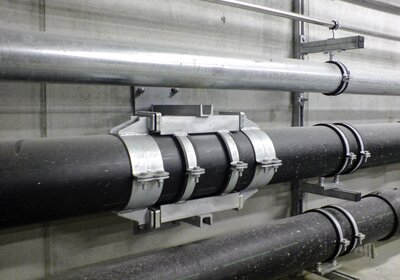
Fixpoint type B for very high forces on a stainless steel pipe: Here, pressure pads are welded in pairs to the pipe in such a way that the console prevents movement in the axial direction. A sound insulation element is located between the pressure pad and the console.
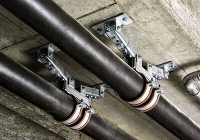
Fixpoints type A are sufficient for forces of medium magnitude. These are equipped with a pair of pressure pads, which are welded to the steel pipe in the picture above. The forces are transferred to the concrete ceiling by means of joint holders.
How long is long?
The example calculation is certainly very simple, but it shows that for longer pipes, fixpoints and sliding elements are anything but cosmetic. But what is long in terms of the need for detailed planning and calculation? Volker Weber, product manager, formulates a rule of thumb: "In smaller pipe systems, for example in single- or two-family houses with straight pipes under 10 m, the normal course of the pipe with its many changes of direction is usually sufficient to compensate for thermal changes in length. In cases of doubt, sliding pipe supports such as sliding pipe clamps ensure that the pipes can move a little. For directional changes, additional care must be taken to provide a sufficiently large bending leg."
Another example of a fixpoint type B on a steel pipe: Here, the pressure pads are each welded on the opposite side of the pipe. For the introduction of large forces into the wall, the profile rail is additionally secured with cross girders.
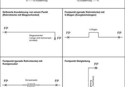
Accordingly, special measures are required for longer pipe sections, larger pipe diameters and higher system temperatures. Sliding elements should be used here or, depending on the installation case, expansion bends or compensators. If sufficient space is available, expansion bends are a good and cost-effective solution. Accordingly, compensators are the method of choice if there is a lack of space. When planning, guide bearings should be provided immediately upstream and downstream of the compensator to prevent the pipe from buckling in the area of the compensator. Fixpoints must also be planned at the ends of the compensated pipe sections. These must absorb both the axial pressure forces and the adjusting force of the compensator.
When selecting the sliding elements, the maximum change in length of the pipe is the design basis. In practice, however, elements with larger sliding distances should be selected, since they are often installed in the middle position, so that the entire sliding path is no longer available at operating temperature. The dead weight of the pipe and the resulting static friction resistance must also be taken into account. This must be overcome during pipe expansion and generates an additional axial force on the holding construction, which can be up to 30 percent of the weight force of the pipe.
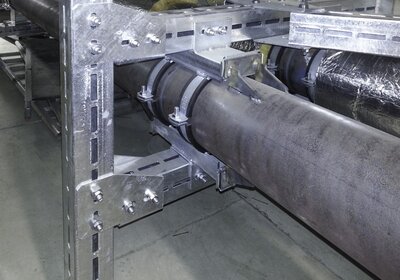
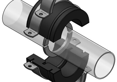
If no pressure pads can be welded on because the pipe is too thin or, as here, made of plastic, fixpoints with clamping connections are used. The forces that can be transmitted are not so high here.
Calculation begins with the selection of fixpoints
Before the sliding elements are designed, the fixpoints must be selected. They fix the pipe at fixed points and ensure a defined - and above all calculable - expansion of the pipe system. Fixpoints can also be set to divide straight lines into shorter sections and thus provide expansion limitation. In the case of risers, they have the task of absorbing the dead weight of the pipe. In this case, pipe clamps only perform as a guiding function. Another important function of fixpoints is to minimize oscillations or rather vibrations of the pipe and to compensate for water hammer. For this purpose, they should be placed as close as possible to the source of the disturbances.
When planning fixpoints, the exact course of the pipe and the constructional conditions must be taken into account. Where are walls, and where could collisions occur if the pipe moves? Is a fixpoint required in front of a fire wall due to excessive movement of the pipe? Each installation requires individual planning, but basic rules can be formulated, which are listed in the info box "Criteria for placing fixpoints".
For chilled water pipes, we offer special insulated fixpoints where the pressure-resistant PUR shell is not penetrated at any point. Instead of pressure pads, weld-on rings are used here. This reliably prevents the formation of condensation water at the fixpoint.
Criteria for the quality of fixpoints
Fixpoints are advantageous if they combine a high load-bearing capacity with good structure-borne sound insulation, as prescribed by DIN 4109 for building construction. In the case of the MEFA fixpoint type A, for example, the load is taken up by sound insulated pressure pads that are to be welded to the pipe. For very high loads, two pairs of pressure pads can also be welded to opposite sides of the pipes, which is then referred to as a fixpoint type B. If it is not possible to weld on the pressure pads, e.g. as with PE pipes, cast iron pipes or very thin-walled pipes, there is a fixpoint variant in clamping design, which is also sound insulated.
The connection to the construction is usually made via a welded fixpoint console. There are also different designs of fixpoint consoles depending on the load size, for high loads in double design and with cross girders.
Further quality criteria for fixpoints are ease of installation - i.e. fast and safe installation with as few additional components as possible - and variable fastening options from which can be chosen depending on the installation situation.
Conclusion
Thermally induced linear expansion becomes particularly critical in the case of large-dimension installations and high system temperatures. To keep pipe movements under control, expansion joints must be provided in such cases. Planning requires precise knowledge of the pipe run and the constructional conditions. Quality criteria for fixpoints are high load-bearing capacity, good sound insulation, uncomplicated installation with as few additional components as possible and variable fastening options.
Writer
Volker Weber, product manager
INFO BOX: Placement of fixpoints
Usefully, set fixpoints allow a reliable prediction of the directions in which a pipe will move when the temperature changes. This also provides the basis for a reliable strength calculation.
INFO BOX: Criteria for placing fixpoints
|
INFO BOX: Thought experiment on thermal expansion
|
For the thermal linear expansion of pipes and, of course, all other prismatic bodies, the following applies: ΔL = 𝛼 L ΔT The coefficient of expansion 𝛼 for steel is 0.012 mm/m K, which, using the numbers from the text, results in 12 mm of length change. If this change in length is to be compensated, the pipe would have to be compressed. The force required for this can be calculated using Hooke's law for elastic deformations. The formula is: F = E ε A E is the modulus of elasticity, which for steel is 210,000 N/mm2. ε stands for the elongation, i.e. ΔL/L, and A for the cross-sectional area. According to the planning aids from our catalog for seamless steel pipes (DIN 2448), the selected pipe with DN100 has an outer diameter of 114.3 mm and a wall thickness of 3.6 mm. This results in a force of around 157 kN. However, this figure is only theoretical and serves to illustrate the high forces involved. Buckling of the pipe is not taken into account here. |

